April 2, 2025

April 2, 2025
In industries where materials are exposed to aggressive environments containing hydrogen sulfide (H?S), ensuring resistance to Sulfide Stress Cracking (SSC) and Stress Corrosion Cracking (SCC) is essential. NACE TM0177, developed by the National Association of Corrosion Engineers (now AMPP), is a globally recognized standard for evaluating the susceptibility of metals to these failure mechanisms. Among its four test methods, Method A, the NACE Standard Tensile Test, plays a critical role in assessing metal performance under uniaxial tensile loading conditions. This blog delves into the principles, procedures, and significance of Method A in determining the environmental cracking resistance of materials used in sour service applications.
First, let’s have a look at NACE TM0177 and the scope of this standard.
NACE TM0177 is a widely recognized standard test method developed by the National Association of Corrosion Engineers (NACE, now AMPP) for evaluating the resistance of metals to sulfide stress cracking (SSC) in environments containing hydrogen sulfide (H?S). This standard provides a set of laboratory procedures to assess the susceptibility of metals, particularly high-strength steels, to hydrogen embrittlement and SSC, which are critical failure mechanisms in sour service conditions.
The primary objective of NACE TM0177 is to determine whether a given metal or alloy can withstand H?S-rich environments without failing due to SSC, a form of environmentally assisted cracking (EAC). This is crucial for industries such as oil and gas, petrochemical, and pipeline transportation, where components are frequently exposed to sour environments.
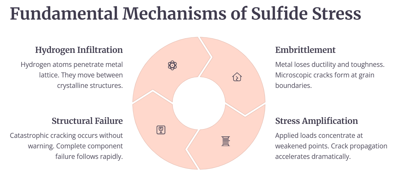
This standard defines procedures for testing metals for resistance to cracking failure under the combined influence of tensile stress and corrosion in aqueous environments containing hydrogen sulfide (H?S). This failure mechanism is commonly referred to as sulfide stress cracking (SSC) when occurring at room temperature and stress corrosion cracking (SCC) when observed at elevated temperatures. Given the variation in cracking behavior across different materials and temperature conditions, the broader term environmental cracking (EC) is used in this standard which includes SSC, SCC, and hydrogen stress cracking (HSC). These are the primary mechanisms of material degradation in H?S-rich environments.
Moving on to the details of NACE Standard Tensile Test,
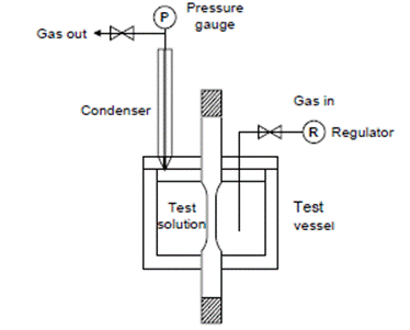
Schematic Arrangement of Test Equipment for Method A—NACE Standard Tensile Test
Method A, known as the NACE Standard Tensile Test, is used to evaluate the resistance of metals to Sulphide Stress Cracking (SSC) under uniaxial tensile loading conditions. This method utilizes a simple, unnotched test specimen with a well-defined stress state. The primary criterion for determining SSC resistance using this method is the time-to-failure of the test specimen.
Specimens subjected to a specific stress level yield a binary failure/no-failure result, which can be further analyzed by testing multiple specimens at varying stress levels to establish an apparent threshold stress for EC. This test procedure is typically conducted at room temperature and atmospheric pressure.
The selection of test specimens for tensile testing is often constrained by the size and shape of the available material. Additionally, the orientation of the test specimen can influence the results and should be documented accordingly.
The standard tensile test specimen is required to have a gauge section diameter of 6.35 ±0.13 mm (0.250 ±0.005 in.) and a length of 25.4 mm (1.00 in.), as specified in ASTM A 370. If necessary, a subsize tensile test specimen may be used, with a gauge section diameter of 3.81 ±0.05 mm (0.150 ±0.002 in.) and a length of 15 mm (0.60 in.).
To maintain the integrity of the specimens before testing, they should be stored in a controlled environment with low humidity, either in a desiccator or immersed in uninhibited oil, to prevent any potential surface degradation.
To minimize stress concentrations and prevent fillet failures, the radius of curvature at the ends of the gauge section must be at least 15 mm (0.60 in.). Additional measures to reduce the likelihood of fillet failures include avoiding undercutting of fillet radii in machined specimens and introducing a slight taper of 0.05 to 0.13 mm (0.002 to 0.005 in.) in the gauge section. This taper ensures that the minimum cross-section is located at the center of the gauge section, improving the consistency of test results.
The test specimen must have sufficiently long ends to accommodate the seals required for the test vessel and to facilitate secure connections to the stressing fixture, as shown in the figure below:
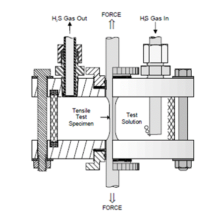
Tensile test specimen in an environmental chamber
Additionally, careful machining or grinding is essential to prevent overheating or cold working of the gauge section, which could alter the material properties. During machining, the final two passes should remove no more than 0.05 mm (0.002 in.) of material to maintain dimensional accuracy and surface integrity.
To ensure consistency in Sulphide Stress Cracking test, the final surface finish of all test specimens must be 0.81 ?m (32 ?in.) or finer. This finish can be achieved through mechanical polishing or electropolishing, provided that the specified roughness requirement is met. If any finishing process other than grinding is used, it must be explicitly reported along with the test data. In cases where electropolishing is employed, the bath conditions must be carefully controlled to prevent hydrogen absorption, which could affect the material properties and test results.
If a standard tensile test specimen cannot be obtained due to material size or shape constraints, a subsize tensile test specimen may be used as an alternative. However, it is important to note that subsize specimens may exhibit shorter failure times compared to standard specimens, potentially impacting the interpretation of results. When reporting test data for subsize specimens, the use and exact dimensions of the subsize specimens must be clearly documented to ensure transparency and comparability of results.
Now, let’s have a look at the identification of the test specimen and its cleaning procedures.
Proper identification of test specimens is essential for accurate tracking and documentation. Stamping or vibratory stenciling may be applied to the ends of the test specimen but must not be used in the gauge section to prevent introducing stress concentrations that could affect test results.
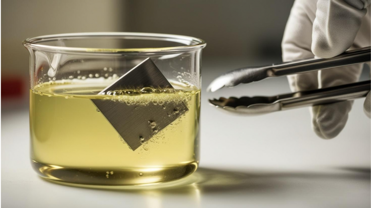
Before undergoing Sulphide Stress Cracking test, specimens must undergo a thorough cleaning process to remove contaminants. This involves degreasing with a solvent followed by rinsing with acetone to ensure a clean surface. After cleaning, the gauge section must not be handled or exposed to contaminants to prevent any alteration in surface properties that may influence test outcomes.
For testing, Test Solution A is utilized, which consists of an acidified and buffered, H?S-saturated aqueous brine solution. The solution is prepared by dissolving 5.0 wt% sodium chloride (NaCl) and 0.5 wt% glacial acetic acid (CH?COOH) in distilled or deionized water (e.g., 50.0 g NaCl and 5.0 g CH?COOH in 945 g of water). The expected initial pH before or after H?S saturation, but before specimen contact, ranges from 2.6 to 2.8.
Each laboratory must follow a documented purging procedure to verify that the pH does not exceed 3.0 after purging. During testing, the pH may increase but must remain below 4.0; exceeding this limit renders the test invalid. Maintaining the specified solution volume-to-specimen surface area ratio and preventing oxygen ingress, as outlined in this standard, will help ensure the pH remains within the acceptable range.
Test Solution A is the default solution for Methods A, C, and D, unless the user or purchaser specifies the use of Test Solution B or C.
Various stress fixtures and test vessels can be used for stress corrosion testing under Method A. The selection of appropriate equipment should be based on key characteristics that ensure accurate and consistent testing procedures.
Tensile tests should be conducted using either constant-load devices or sustained-load devices such as proof rings or spring-loaded systems, in accordance with ASTM G 49. All loading devices must be calibrated to ensure precise load application, with an allowable error of no more than 1.0% within the calibration range. Additionally, the design of the loading device must prevent torsional loads, as unintended stress components can affect the accuracy of test results.
When sustained-load devices are used for testing susceptible materials, cracks may initiate and propagate only partially through the specimen. This necessitates a visual examination of the test specimen to identify any part-through cracks. However, this determination can be challenging if cracks are small, sparse, or obscured by corrosion deposits. In contrast, testing with constant-load devices provides a more definitive result, as susceptible materials will separate completely, clearly indicating material failure without relying on the identification of partial cracks.
For constant-load testing, dead-weight testers can be used. These systems are capable of maintaining constant pressure on a hydraulic cell, ensuring uniform loading throughout the test duration.
Sustained-load tests can be performed using spring-loaded devices and proof rings, provided that relaxation in the fixtures or test specimen results in only a minor reduction in the applied load. When using proof rings, specific procedures must be followed to ensure accuracy. Before calibration, proof rings must be preconditioned by subjecting them to 10 cycles of loading at 110% of their maximum load rating.
The applied load on the tensile test specimen must fall within the proof ring’s calibrated load range. To ensure accurate load measurement, the proof ring should exhibit a deflection greater than 0.6% of its diameter and at least 0.51 mm (0.020 in.). If the deflection is below these thresholds, the calibration deflection, calibration load, and test load must be explicitly stated.
A significant decrease in proof ring deflection during testing may indicate one or more of the following:
(a) Crack initiation and propagation in the test specimen,
(b) Plastic deformation (yielding) of the test specimen, or
(c) Stress relaxation within the system.
To monitor these effects, deflection measurements should be taken periodically during the test or at its completion, particularly when the applied stress is within 10% of the material’s yield strength.
Proper electrical isolation of the test specimen from other metals in contact with the test solution is crucial to prevent interference with the test results. The seals around the test specimen must provide electrical isolation, remain airtight, and allow specimen movement with minimal friction.
In cases where the entire test fixture is submerged in the test solution, the stressing fixture should either be made of the same material as the test specimen or, if constructed from a different material, be electrically isolated from it. If necessary, the stressing fixture may be coated with a nonconductive impermeable layer to prevent unwanted interactions.
To maintain proper test conditions, the test vessel should be sized to ensure a test solution volume of 30 ±10 mL per cm² of the test specimen’s surface area. This volume ratio is essential to maintain the chemical environment required for accurate and reproducible results.
The testing sequence begins with measuring the minimum gauge diameter of the tensile test specimen to ensure precise calculations for applying the desired stress level. Once the required dimensions are recorded, the tensile test specimen load is determined accordingly.
Before initiating the test, the test specimen must be thoroughly cleaned to remove any contaminants. It is then placed inside the test vessel, which must be sealed properly to prevent air ingress during the test, ensuring the integrity of the test environment.
The application of load can be performed either before or after the test vessel is purged with an inert gas to eliminate oxygen and maintain a controlled environment. The specimen may be subjected to stress in incremental steps based on yield strength or applied load, depending on the test requirements.
Careful attention must be given when applying the load to prevent exceeding the intended stress level. If the applied load surpasses the desired value, the test must either continue at the new load or be discarded and restarted to ensure the validity of the results.
Once the test vessel is sealed, it must be immediately filled with the test solution, ensuring that the gauge section of the test specimen is fully immersed. To maintain an oxygen-free environment before the introduction of H?S, the test solution must be completely deaerated using one of the following methods:
Following deaeration, the test solution must be saturated with H?S by purging it at a rate of at least 100 mL/min for at least 20 minutes per liter of solution. Throughout the test, a continuous flow of H?S must be maintained at a low rate (a few bubbles per minute) through the test vessel and outlet trap. This continuous flow ensures that the H?S concentration remains stable and that a slight positive pressure is maintained to prevent air ingress through small leaks, preserving the integrity of the test environment.
The presence of oxygen contamination in the test solution is indicated by a cloudy or opaque appearance when H?S gas enters the test vessel. If this occurs, the test is considered invalid and must be disqualified. In such cases, the test specimen must be removed and cleaned, and the entire test solution preparation, transfer, and deaeration process must be repeated to ensure an oxygen-free environment before restarting the test.
The test shall be terminated either upon failure of the tensile test specimen or after 720 hours, whichever occurs first. If necessary, additional tensile test specimens may be tested to accurately determine the no-failure stress level, ensuring a comprehensive assessment of material behavior under the specified conditions.
After the exposure period, the gauge section of non failed tensile test specimens must be thoroughly cleaned and inspected for any evidence of cracking. Any test specimens exhibiting cracks should be documented accordingly.
Failure is determined based on one of two criteria:
(a) Complete separation of the tensile test specimen, or
(b) Visible cracks on the gauge section when examined at 10X magnification after the 720-hour test duration.
To further evaluate cracking, advanced investigative techniques such as metallography, scanning electron microscopy (SEM), or mechanical testing may be employed. If these techniques confirm that the observed cracks are not a result of environmental cracking (EC), the test specimen is considered to have passed.
Additionally, the time-to-failure can be accurately recorded using electrical timers and microswitches, ensuring precise data collection throughout the test duration.
The test results must include a detailed record of the time-to-failure and no-failure data, along with any visual observations of surface cracks on the test specimens at the conclusion of the test. These results should be documented for each stress level to ensure a comprehensive evaluation of material performance.
Additionally, the chemical composition, heat treatment details, mechanical properties, and any other relevant test parameters must be reported. This information provides essential context for analyzing the test results and comparing material behavior under different conditions.
For clarity and consistency, the test data should be recorded in the recommended tabular format shown in Table 1. Alternatively, the results may also be presented using semilog graph paper, which can help illustrate trends and relationships in the data more effectively.
The load required for stressing the tensile test specimens must be determined using Equation (2):
P=S×A
where:
This equation ensures that the appropriate load is applied based on the desired stress level and the measured cross-sectional area of the test specimen. Accurate stress calculations are essential for maintaining test consistency and ensuring reliable material performance assessments.
The NACE Standard Tensile Test (Method A) serves as a fundamental tool for assessing the resistance of metals to sulfide stress cracking in sour service conditions. By subjecting materials to controlled uniaxial tensile stress in H?S-saturated environments, this method provides valuable insights into their susceptibility to cracking failure. The rigorous test procedures, including specimen preparation, load application, and post-test evaluation, ensure reliable data for material selection and performance validation.
Adhering to the NACE TM0177 guidelines is essential for industries that prioritize operational safety and asset longevity in corrosive environments. The test results contribute to informed decision-making in alloy selection, enhancing the durability of components exposed to H?S.